In 2019 we moved to a new home and had to leave our old fort behind. There was nothing to do but start again! We got more ambitious this time around.
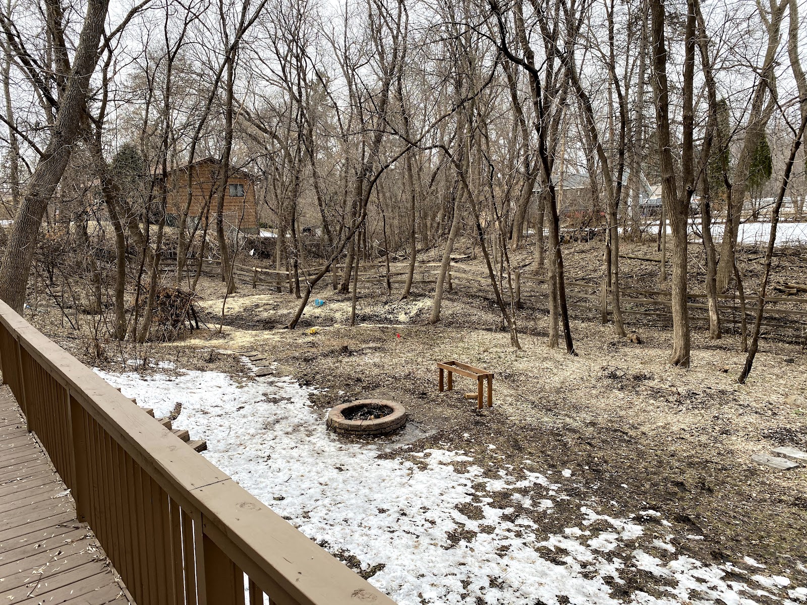
We picked a location far enough from the main house to feel adventurous, but close enough that we could easily see the fort from the house and house from the fort.
Fort Location
I did the initial design in SketchUp. With some help from my dad, I decided to use four 6"x6" posts as the main supports (upgrading from the 4"x4"s used in the previous fort).
Fort Scale
Since we live in Minnesota, we had to dig down 4' for each of the four posts to avoid heaving risk in winter.
Posts Poured
With help from the neighbors we set up the posts and braced them into position.
I don't own a construction helmet, so I used a bike helmet
We notched out the posts to mount two 2"x8" ledger boards.
We lag bolted the ledger boards to the posts, then hung 2"x6" joists between them. We used ledger strips, rather than joist hangers, to save money (the size difference between the ledger board and joists allow this approach).
We put down plywood decking and decorated it.
We installed a temporary roof to keep rain from spoiling the plywood decking.
Adding a temporary roof. Also shown, rails to keep people from falling out
We used the fort as-is for quite a while, since it made a great place to see the yard and the kids enjoyed playing in it.
The gully flowing, as seen from the fort
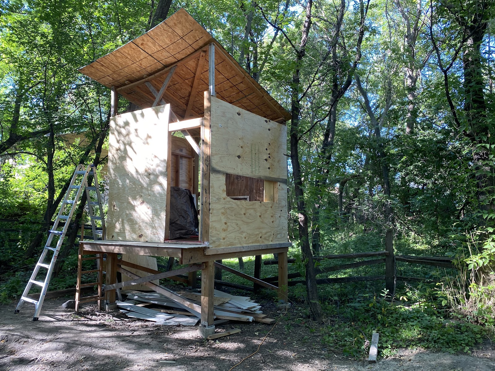
Eventually (a couple of years later!) we decided it was finally time to add some walls. My dad and I stick-built the walls from 2"x4"s and the kids helped with sheathing.
Fort with sheathing and a hole cut for a window
We used house wrap left over from siding our main home, and some friends gave us a couple of old windows.
My dad did the trim and siding on the front.

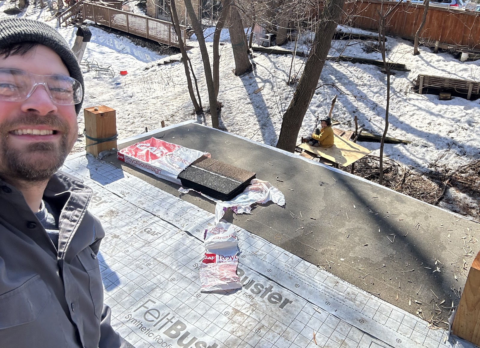
It was time to replace the temporary (now years old) roof with a real roof. We still plan to add a rooftop patio, so the real roof had to be a little shorter than the top of the 6"x6" posts.
I managed to finish shingling the new roof just before winter in 2022.
My dad built a beautiful custom front door.
Components of the custom lock
Which required a bit of welding to make a custom mounting bracket for the magnetic lock.
Magnetic lock mounted with welded steel bracket
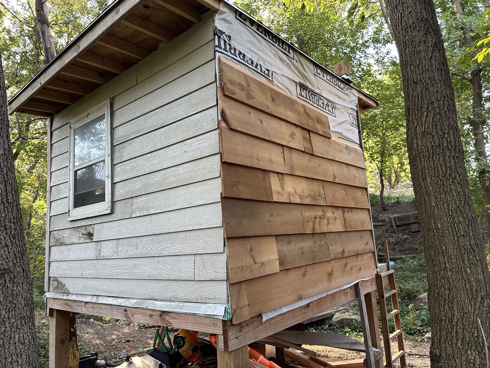
My dad and I have nearly finished the siding (different on every side, because we're reusing old material)
Different siding on each side
I added some interior and exterior lights
Now we're working on the interior. Stay tuned!

